Scene assets are transformed into reviewed landmarks, then into image and video benchmark
tasks through a stage-by-stage pipeline with explicit handoff files and quality-control
points.
Release Funnel
The released split is obtained through explicit filtering stages
These counts come from the current release statistics and summarize how raw scene assets are
narrowed into the released split.
The funnel below should be read as a quality-controlled release path rather than a simple
downsampling process. UAV-DualCog first starts from a broader reviewed scene pool, then
progressively restricts that pool through landmark validation, task construction
constraints, and benchmark split selection until the public release retains only the rows
that satisfy the intended evaluation contract.
In practice, the largest reductions do not come from rendering image or video tasks
themselves, but from the earlier stages that determine whether a scene is suitable for
release, whether a landmark is sufficiently stable and recognizable, and whether a mission
or observation should be exposed as benchmark-facing media. This is why the left-hand funnel
is best interpreted as evidence of curation rigor: each retained count already reflects
review, filtering, and release-boundary decisions rather than raw generation volume alone.
The Stage Snapshot on the right complements these counts by summarizing the media contract
that the released benchmark actually exposes. Together, the funnel and the snapshot explain
both how much data survives each stage and what form that surviving data
takes once it reaches public use, including image resolution, frame sampling, aspect-ratio
consistency, and compression policy. Unlike many earlier embodied QA benchmarks that only
release relatively low-resolution observations, UAV-DualCog preserves 4K-grade source
imagery and adopts the internationally standardized DCI 4K 4:3 setting, which is also
compatible with mainstream UAV capture configurations such as DJI Mavic 4 Pro. This allows
the same release to support evaluation under multiple resolution settings: researchers may
retain the original high-resolution assets for fine spatial reasoning tests or derive
lower-resolution variants for controlled efficiency comparisons without changing benchmark
semantics.
Construction Funnel
Counts exported from the current release statistics.
Raw Landmark Candidates2626.00
Stage 1 + Stage 2 candidate pool
Reviewed Valid Landmarks746.00
After review keep/discard and semantic annotation
Released Split Landmarks512.00
Landmarks selected into UAV-DualCog
Stage 4 Samples4096.00
Image QA rows exported from the released split
Stage 3 Samples2048.00
Video benchmark rows exported from the released split
Construction Funnel. The largest reductions happen before the benchmark rows are finalized: scene review narrows the raw environment pool first, then landmark validation and task-side filtering further trim the candidate space before public export. By the time the release reaches 512 landmarks, 4096 image rows, and 2048 video rows, each retained item has already passed multiple rounds of geometric, semantic, and release-boundary screening rather than simple random subsampling.
Stage Snapshot
The construction chain stays compact because each stage has a narrow role and a concrete handoff artifact.
DCI 4K
Image & Frame Capture
4096×3072 for both video-task frame capture and image-task asset rendering
4:3
Aspect Ratio
used consistently across released media and aligned with common UAV capture settings
JPEG quality 80
Compression Policy
balances image quality and file size in the public release
1080P
Stage 3 Video
1440x1080 · 10 Mbps · H.264 / MP4 · YUV420p, with on-demand resolution support up to 4096×3072
10 FPS
Video Frame Rate
captures rapid action changes while remaining practical for MLLM temporal reasoning
Stage Pipeline
The construction story is best read as four linked stages rather than scattered implementation notes
UAV-DualCog is constructed through a four-stage process that starts from scene-scale point
cloud collection, moves through landmark review and structured annotation, then branches
into behavior-driven video-task construction and landmark-centered image-task construction.
The figure below gives the end-to-end pipeline view, while the summary cards that follow
condense each stage into its role, inputs, outputs, and benchmark-facing handoff.
Construction Pipeline. The benchmark construction process links scene scanning, landmark review, behavior-driven mission generation, and image-task assembly into one explicit four-stage pipeline.
STAGE1
Scene Point-Cloud Collection and Semantic Fusion
Build a scene-level geometric backbone aligned with RGB, segmentation, LiDAR, and pose data.
Inputs. Scene config, sampled poses, simulator-side RGB/segmentation/LiDAR streams
Build a scene-level geometric backbone aligned with RGB, segmentation, LiDAR, and pose data.
Stage 1 starts from the simulator scene itself together with the runtime configuration
that defines sensor settings, sampling bounds, altitude, and pose coverage. The goal is
not to generate benchmark questions directly, but to reconstruct a
stable scene-level geometric backbone that later stages can mine
repeatedly without returning to image space.
In the current implementation, this stage follows the same logic described in the paper:
multi-pose sampling, raw chunk capture, and global semantic fusion. RGB, segmentation,
LiDAR, and pose metadata are captured at every sampled pose, then transformed into a
unified scene coordinate system so that semantic and instance identities remain attached
to the fused point cloud. The result is a scene-scale representation that Stage 2 can
split directly into landmark candidates rather than re-detecting objects from scratch.
The key output of Stage 1 is therefore not a benchmark row but a
geometric substrate. By the time this stage finishes, every released
scene already has a stable map boundary, fused point cloud, global coordinate system, and
scan preview record. That shared spatial backbone is what lets later
stages reason about landmark visibility, relative position, orbit feasibility, and scene
coverage without repeatedly solving low-level mapping problems.
Inputs
Scene configs define MapBound, altitude, yaw sweep, and runtime capture
parameters; each sampled pose records synchronized RGB, segmentation, LiDAR, and pose
metadata.
Core Transform
Raw chunks are fused into a scene-scale semantic point cloud while preserving
semantic and instance identities, so Stage 2 can aggregate landmark candidates
directly from geometry-aware assets.
Outputs
The released handoff is a set of scene-scale assets such as fused point-cloud files,
scan preview media, and scene metadata that keep Stage 1 coverage auditable before
landmark mining begins.
python scripts/flightmvstg/stage1_collect_pcd.py --config configs/flightmvstg/task_airsim_env_7.yaml --mode all --scene-id env_7 --engine airsim
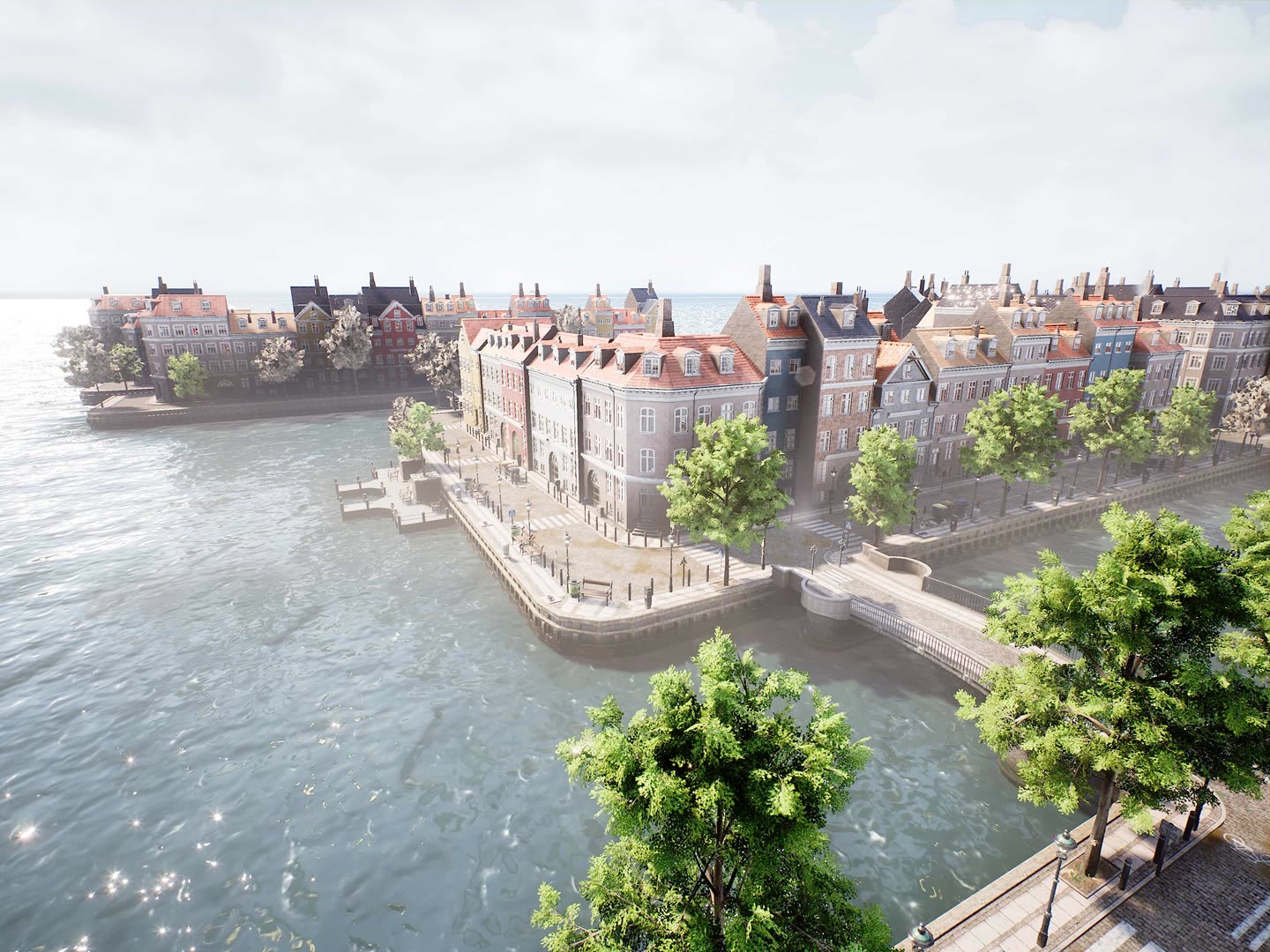
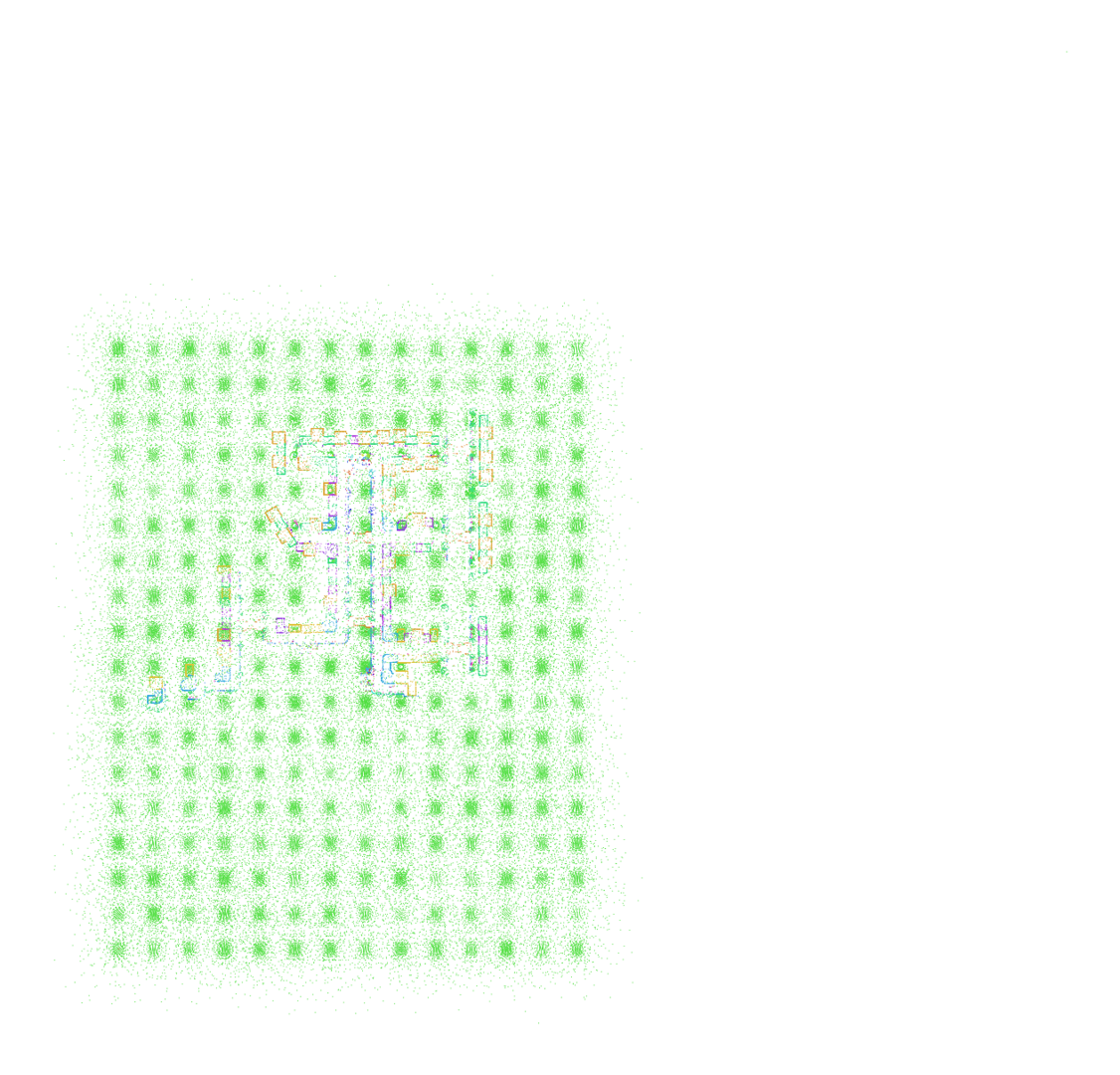
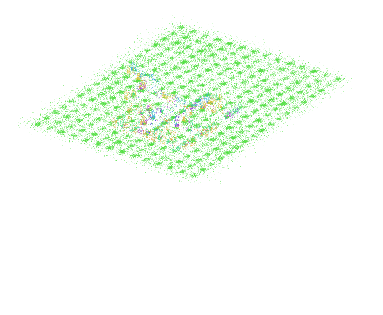
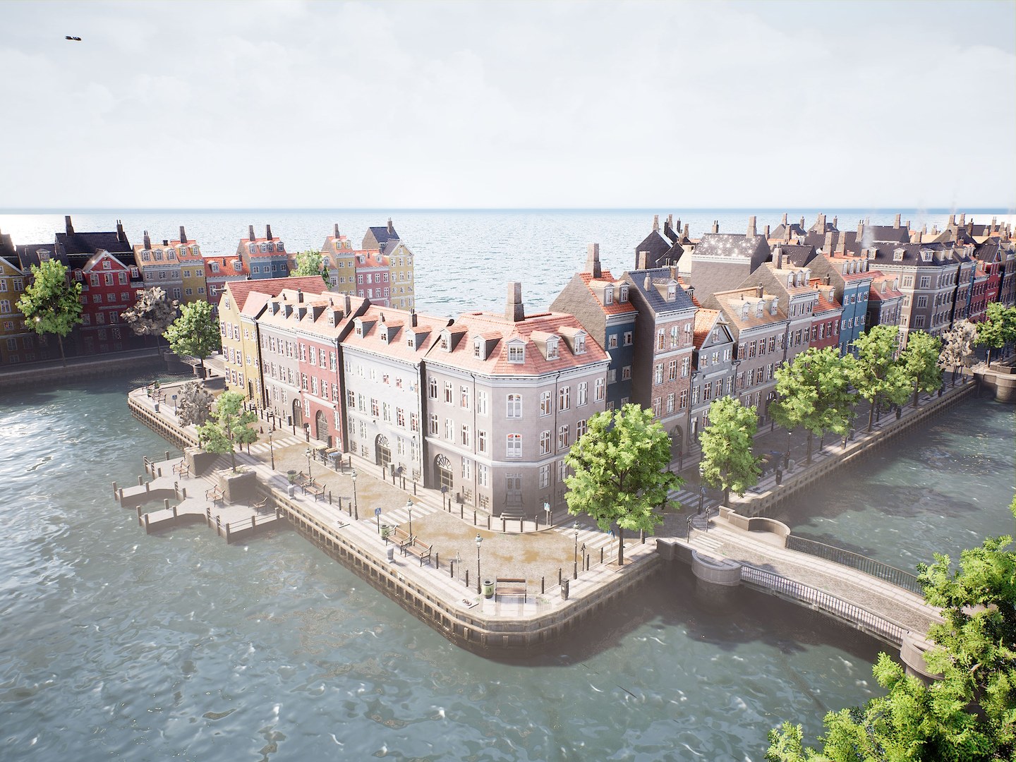
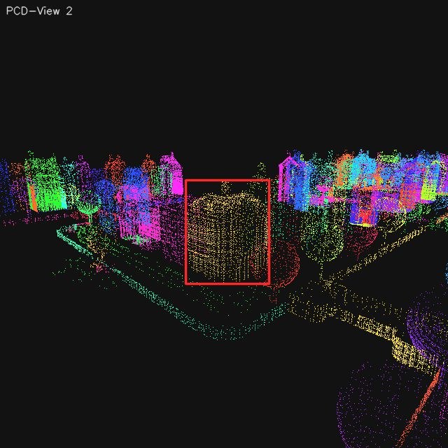
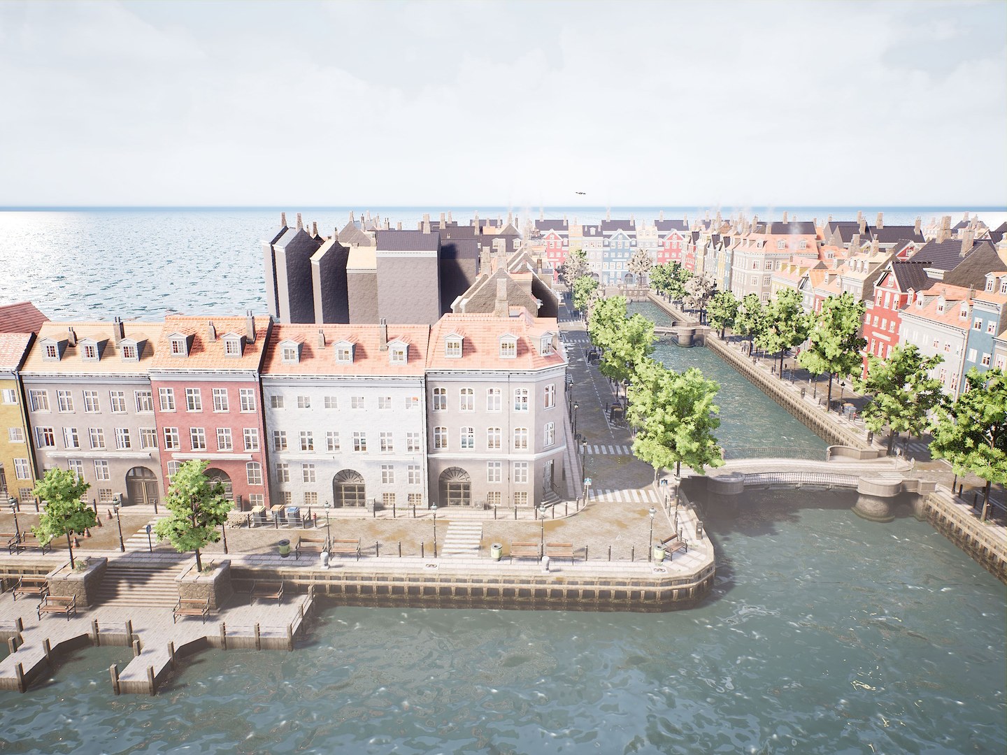
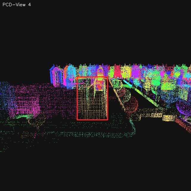
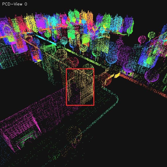
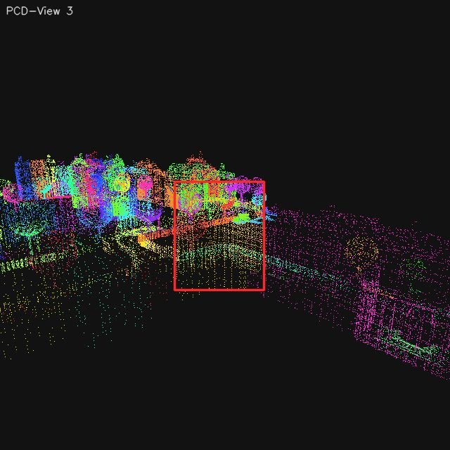
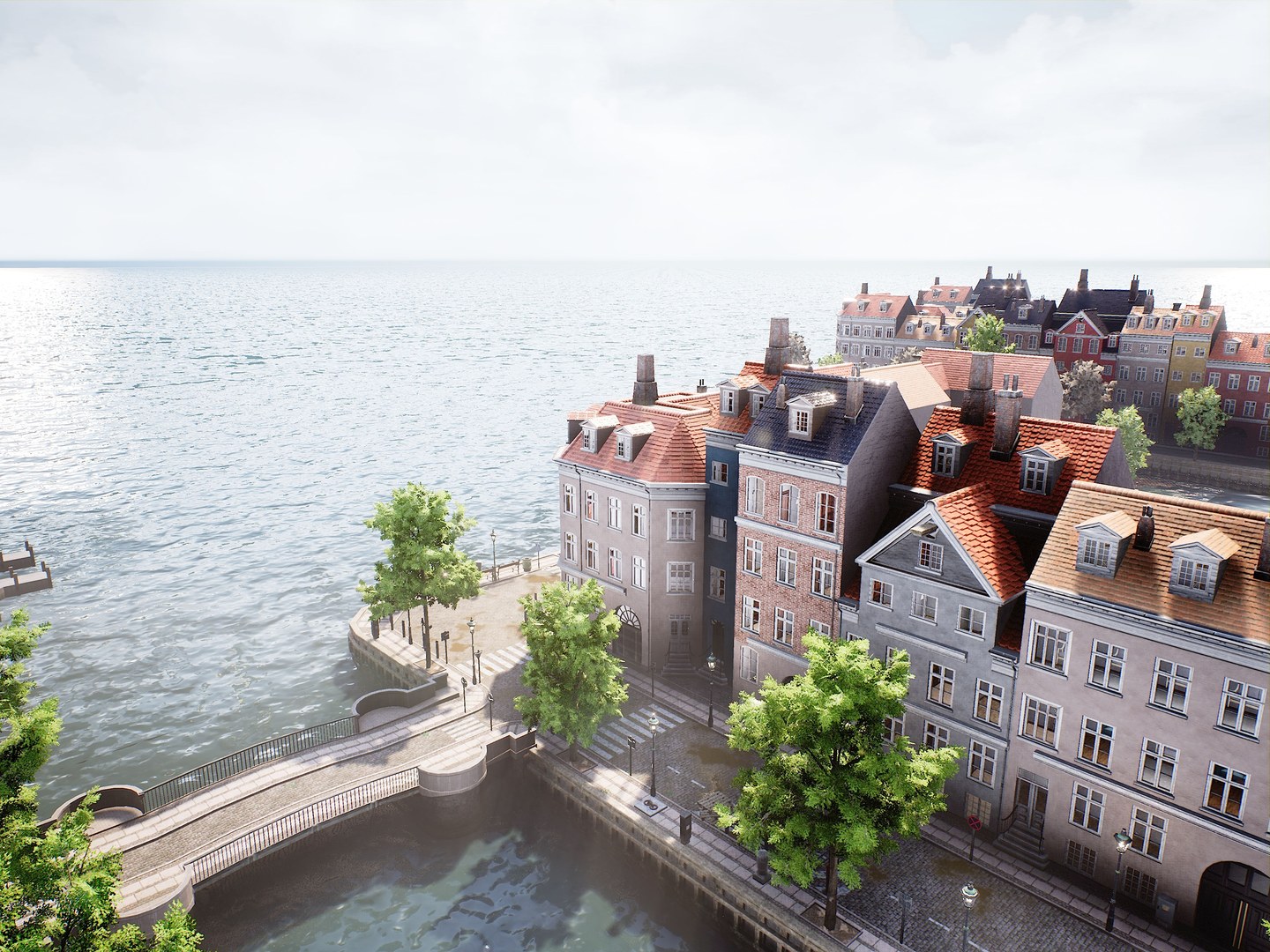
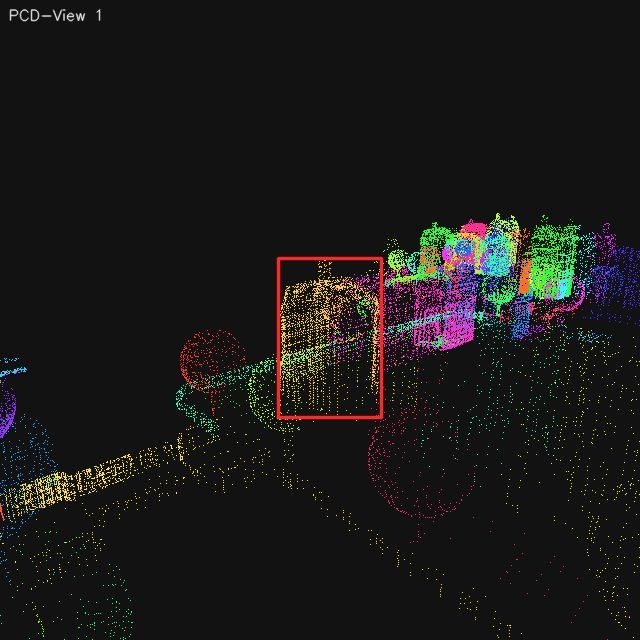
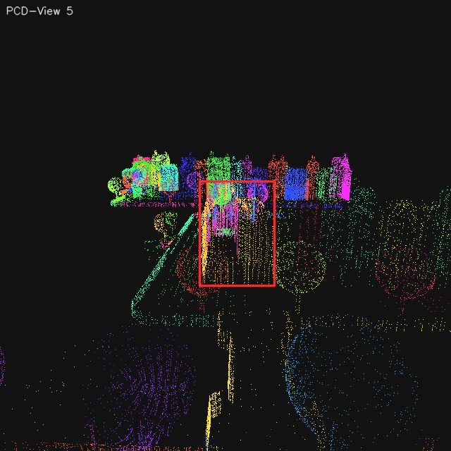
The scene scanning library below exposes benchmark-facing panoramas for the released test
scenes while keeping Stage 1 metadata visible. Each entry now combines two released RGB
scene snapshots with two segmented point-cloud panoramas rendered in top-down and oblique
views, together with the configured scene boundary, mapped area, and the complete
unscreened landmark-candidate count that Stage 2 begins from.
ENV 7 · Waterfront City
Two RGB scene snapshots + two segmented point-cloud panoramas + Stage 2 raw candidate pool
Scene Boundaryx[-219, 191] · y[-270, 268] · z[-50, 52]
Mapped Area220580 m²
Raw Landmark Candidates167
Reviewed Valid Landmarks86
RGB Top-Down PanoramaRGB Oblique PanoramaSegmented Point Cloud Top-DownSegmented Point Cloud Oblique
1 / 12
Scene Scanning Library. Two benchmark-facing RGB scene snapshots and
two segmented point-cloud panoramas are shown for each released test environment together
with Stage 1 boundary metadata and the unscreened Stage 2 candidate pool.
Stage 2
Landmark Review and Semantic Annotation
Turn the fused scene cloud into a reviewed, semantically named landmark pool.
Stage 2 consumes the fused semantic and instance-aware cloud from Stage 1 and converts it
into reviewed landmark assets. The pipeline first groups points by
semantic class and instance identity, then renders multiview RGB and point-cloud
evidence around each candidate so that geometric structure, appearance, and view
direction are all available before any benchmark task is built.
For each landmark candidate, the pipeline computes eight orbit-view capture
poses from the 3D bounding box and instance center, covering
the canonical directions front, front-right, right, back-right, back, back-left,
left, and front-left. The associated segmented point-cloud views are then used to
perform occlusion-aware validity checks, so heavily blocked or
non-informative directions can be excluded before benchmark-facing landmark assets are
finalized.
This is the stage where scene geometry becomes benchmark object assets.
Review removes unstable or uninformative candidates, confirms the main view, and finalizes
the reviewed landmark manifest used by both Stage 3 and Stage 4. After
review, the pipeline runs a constrained auto-label prompt to add coarse
category, fine-grained subcategory, and a short discriminative description that later
prompts can reuse.
The important shift is that Stage 2 turns a fused but still machine-oriented scene map
into benchmark-facing semantic objects. Candidate aggregation, multiview
review, and prompt-constrained annotation are linked in one chain: only after geometry,
visibility, and main-view consistency are confirmed does the pipeline allow a landmark to
receive the semantic fields that later prompt templates depend on.
Step 1 · Candidate Aggregation. The pipeline first partitions the fused
semantic cloud by semantic class and instance identity. Each resulting candidate is then
packaged with multiview RGB evidence, point-cloud views, 3D center metadata, and 3D box
support so that later review decisions are made against geometry-aware evidence rather
than isolated screenshots. At this stage the pool is intentionally permissive: the goal
is to surface all plausible landmark candidates before benchmark-facing filtering begins.
Step 2 · Review and Main-View Confirmation. Human review then removes
unstable or uninformative instances, confirms the most representative main view, verifies
one landmark-centric direction anchor, and checks bbox validity. The main view is not
required to be the front image; it is simply the clearest and most
benchmark-facing reference view. Once that anchor direction is confirmed, the remaining
seven directions are derived automatically in the fixed orbit order rather than being
edited independently. At this step, reviewers also manually remove unusable view
images that remain visually ambiguous, severely occluded, or otherwise unsuitable
even after the earlier geometric filtering. Candidates can be dropped immediately, but a
landmark is only kept after the main-view and direction checks are complete. The accepted
pool is frozen in the reviewed landmark manifest (valid_instances.json),
which becomes the only stable Stage 2 handoff consumed by both later stages. In practice
this step turns a broad candidate inventory into a controlled landmark repository whose
direction labels, representative views, and spatial references can be trusted downstream.
Step 3 · Prompt-Constrained Semantic Annotation. After geometric review,
the pipeline runs a constrained auto-label prompt to enrich each landmark with benchmark-
facing semantics. This is not free-form captioning: the prompt explicitly constrains
category choices, subtype naming, and JSON formatting so that landmark semantics remain
short, discriminative, and machine-parseable. The result is a semantic layer that later
prompt templates can reuse directly without re-describing each landmark from scratch.
In practice, Stage 2 Step 2-4 are completed in the internal review web.
That interface is where reviewers perform candidate screening, main-view confirmation,
single-direction anchoring, invalid-view cleanup, auto-label launch, and final semantic
audit. The command line remains useful for collection and standalone auto-label reruns,
but the web is the recommended working surface whenever view quality and semantic
correctness need to be judged together from visual evidence.
Layer 1 · Coarse Category. A closed eight-class ontology anchors every landmark before later task generation.
The prompt must choose exactly one coarse category from the fixed benchmark-facing list: building, vehicle, public_facility, urban_landscape, transport_infrastructure, industrial_infrastructure, vegetation, or other.
Layer 2 · Fine-Grained Subcategory. The second layer stays flexible but must remain category-consistent and generic.
Subcategories cannot be proper nouns or brands; they act as reusable landmark types such as mid-rise building, trash bin, shipping container stack, or deciduous tree.
Layer 3 · Discriminative Description. A short noun phrase captures the identifying cues that later prompts can reuse.
Descriptions must stay under twenty words while preserving subtype, color, shape or texture, and any local visual cue that helps distinguish nearby landmarks.
The reviewed landmark scanning library below makes that Stage 2 handoff concrete: it shows
each retained landmark view together with the paired segmented point-cloud
rendering captured from the same scanning pose. This is the evidence basis from
which later prompt templates, mission planners, and image-task constructors all reuse
Stage 2 landmark assets after review and semantic labeling are finalized.
Mid Rise Building
Building · Mid Rise Building · ENV 7
light gray mid-rise building with red tiled roof and dormer windows
RGB
Point Cloud
Front
RGB
Point Cloud
Front Right
RGB
Point Cloud
Right
Occluded / Invalid
Occluded / Invalid
Back Right
RGB
Point Cloud
Back
Occluded / Invalid
Occluded / Invalid
Back Left
RGB
Point Cloud
Left
RGB
Point Cloud
Front Left
Landmark Scanning Library. Reviewed landmark-centric RGB side views are
shown together with their corresponding segmented point-cloud views, preserving the
scan-level evidence that underlies later image and video task construction.
Auto-Label Prompt Package
System Prompt
You are an aerial landmark recognition expert. Only use image evidence.
- class_name: {class_name or '(empty)'} (user-filled weak hint from Step 2, optional)
- images: up to 4 views (front/back/left/right preferred, some directions may be missing)
- Each uploaded image has a red bounding box marking the landmark, and the side label (e.g., 'Visible Side: Front (Landmark-centric)') at the top-left corner shows the visible side of the landmark in the object-centric (landmark-centric) frame.
category candidates (must choose from list):
[building, vehicle, public_facility, urban_landscape,transport_infrastructure, industrial_infrastructure, vegetation, other]
subcategory requirements:
- flexible generic subtype, not a proper noun or brand name
- must stay category-consistent
- examples below are illustrative only; use other common descriptive terms or phrases if they better match the landmark
• building: low-rise building, mid-rise building, high-rise building, warehouse, pagoda, chapel, factory shed, rural farmhouse, glass skyscraper, brick schoolhouse
• vehicle: sedan car, delivery van, city bus, cargo truck, motorcycle, construction excavator
• public_facility: street lamp post, bus shelter, public bench, trash bin, fire hydrant, antenna
• urban_landscape: sculpture, plaza, fountain, city square, urban garden, landscape installation, signboard, billboard, advertising board, wayfinding sign, landmark signage
• transport_infrastructure: arch bridge, overpass, railway track, tunnel entrance, roundabout, pedestrian crosswalk, subway station entrance, traffic island, railway platform
• industrial_infrastructure: shipping container stack, oil storage tank, grain silo, crane tower, pipeline
• vegetation: deciduous tree, coniferous tree, palm tree, shrub cluster, hedge row, grassy lawn
• other: temporary tent, rubble pile, playground slide, inflatable archway, construction barrier
description constraints (`description`):
- one noun phrase, <= 20 words
- must include: subcategory, color, shape/texture
- may include surrounding relation, visible text/pattern cues to distinguish the landmark
- positive examples:
- dark red middle-rise building with white neon light featuring the word "HOTEL" on the top
- gray pagoda-like tower with layered roof edges beside roadside trees
- white arch bridge with curved span above a narrow river channel
- dark stone obelisk with sharp top in open paved square
Output JSON (no extra explanation text):
{
"category": "building|vehicle|public_facility|urban_landscape|transport_infrastructure|industrial_infrastructure|vegetation|other",
"subcategory": "...",
"description": "...",
"confidence": 0.0
}
Outputs and Bridge
The released Stage 2 outputs live in the raw and reviewed landmark bundles; reviewed
RGB views, main-view tags, semantic layers, and short descriptions then become the
common substrate reused by Stage 3 and Stage 4.
Compose missions, repair trajectories, render benchmark videos, and export video manifests and metrics.
Stage 3 begins from reviewed Stage 2 landmarks and an explicit two-layer behavior system.
In the current single-landmark release, each valid landmark is bound to one atomic mission
and one composite mission. Those missions are not just labels: they expand into executable
trajectories, camera-control programs, temporal supervision tracks, and final benchmark
manifest rows.
The flight-mode library is designed as a benchmark primitive rather than
a loose collection of cinematic motions. The intent is to keep released trajectories close
to common UAV operating scenarios, so that the resulting video tasks reflect recognizable
drone behavior patterns instead of synthetic camera sweeps with little operational
meaning. At the low level, the atomic motions borrow from the design logic behind DJI's
automated “MasterShots”-style capture patterns, where approach, orbit, rise, and mapping
maneuvers are defined as reusable camera-flight units. At the high level, the
hierarchical flight-mode design organizes composite classes around common
inspection and mapping needs, so that the benchmark's temporal reasoning tasks remain tied
to realistic patrol, inspection, and surveying workflows.
Composite relations
Gradual Approach
Gradual Depart
Circular Orbit
Figure-Eight Orbit
Spiral Orbit
Square Orbit
Triangular Orbit
Surface Mapping
Comet Trajectory
Sky Rise
Behavior Hierarchy. Composite inspection classes are instantiated by
chaining atomic maneuvers, and the highlighted links show which primitives each composite
template reuses in the released Stage 3 library.
The implemented chain is mission generation, trajectory search, trajectory repair, video
recording, and temporal task organization. Collision checks and safety buffers can
trigger radius, height, or scan-width adjustments before a trajectory is accepted, so the
final videos are filtered task assets rather than naïve recordings of an idealized path.
Parallel rendering is also scheduled to keep missions spatially separated and reduce
multi-UAV contamination in the frame.
Once rendering succeeds, Stage 3 exports both mission-level supervision bundles and the
benchmark-facing datasets used for Flight Behavior Recognition and Temporal
Localization and Landmark Visibility Counting and Interval Reasoning.
Archived 4K frame captures and released 1080P H.264 MP4s
are separated on purpose, which lets the benchmark keep high-resolution supervision
upstream while distributing efficient evaluation videos downstream.
In other words, Stage 3 is where motion programs become auditable temporal tasks. The
stage has to satisfy two goals at once: trajectories must remain executable under
collision and safety constraints, and the final media must preserve enough temporal
structure that interval localization remains meaningful for large multimodal models. That
is why mission repair, behavior templating, and supervision export are treated as one
connected pipeline rather than three independent utilities.
The media contract used at this stage is therefore worth exposing directly. Internally,
missions still retain higher-resolution archived frame captures for supervision and
refresh, while the released benchmark distributes a lighter 1080P H.264 video stream at a
fixed frame rate. This separation keeps temporal evaluation efficient for public use while
preserving enough upstream visual detail to support rerendering, inspection, and
higher-resolution downstream analysis when needed.
The Stage 3 internal web is used here as an interactive mission and task
workbench. It exposes pages for the behavior library, mission generation, candidate
review, manifest browsing, experiments, result inspection, and metrics. This makes it
well suited for qualitative verification and targeted reruns, whereas
task_pipeline.py remains the recommended interface for batch
selection, data export, render, and released-scale experiment phases.
DCI 4K
Capture Frames
4096×3072 archived frames are retained for upstream supervision and rerender flexibility
1080P
Released Video
1440x1080 · 10 Mbps · H.264 / MP4 · YUV420p
10 FPS
Frame Rate
keeps rapid UAV motion changes visible while remaining practical for MLLM temporal reasoning
Stage 3 Media Specs. Mission rendering retains 4K-grade archived frame
captures upstream, while the released benchmark exposes 1080P H.264 videos at a fixed 10
FPS evaluation contract.
Mission Expansion and Repair
Composite and atomic behavior templates expand into executable trajectories, then pass
through repair routines that can adjust radius, altitude, or scan width before render
so that accepted missions remain physically valid and visually clean.
Format Constraints and Handoffs
Mission folders preserve a mission supervision bundle
(task_data.json, frames_manifest.json, and
frame_index_map.json) alongside the final video, while released datasets
keep semantic answers and interval targets as separate fields so temporal quality can
be scored independently.
Outputs
The public handoff includes per-scene dataset manifests and mission folders; the
scene-level dataset manifest is the benchmark-facing interface, while each
mission-level task_data.json keeps the denser temporal supervision
contract.
Track the landmark while moving forward, descending gradually, and approaching from a forward oblique direction.
Parameter
Default
Range
Step
Choices
Source
Travel Distance (m)
40
30 to 120
10
-
default
Descent (m)
15
5 to 40
5
-
default
Yaw Offset (deg)
0
-35 to 35
5
-
default
Speed (m/s)
20
15 to 25
1
-
default
Gaze Pitch (deg)
-12
-45 to 0
3
-
default
Camera Mode
landmark_track
-
-
look_forward
override
Step 2
Circular Orbit
circular_orbit · Orbit
Orbit the landmark with a radius extension around the target center.
Parameter
Default
Range
Step
Choices
Source
Extension (m)
12
4 to 36
2
-
default
Arc (deg)
180
45 to 720
90
-
default
Direction
cw
-
-
cw, ccw
default
Altitude Offset (m)
8
-20 to 40
2
-
default
Speed (m/s)
20
15 to 25
1
-
default
Camera Mode
look_forward
-
-
look_forward
override
Gaze Pitch (deg)
0
0 to 0
1
-
default
Step 3
Circular Orbit
circular_orbit · Orbit
Orbit the landmark with a radius extension around the target center.
Parameter
Default
Range
Step
Choices
Source
Extension (m)
12
4 to 36
2
-
default
Arc (deg)
180
45 to 720
90
-
default
Direction
cw
-
-
cw, ccw
default
Altitude Offset (m)
8
-20 to 40
2
-
default
Speed (m/s)
20
15 to 25
1
-
default
Camera Mode
landmark_track
-
-
look_forward
override
Gaze Pitch (deg)
0
0 to 0
1
-
default
Step 4
Gradual Depart
gradual_depart · Inspection
Track the landmark while moving backward, rising gradually, and departing toward a rear oblique direction.
Parameter
Default
Range
Step
Choices
Source
Travel Distance (m)
40
30 to 120
10
-
default
Rise (m)
15
5 to 40
5
-
default
Yaw Offset (deg)
0
-35 to 35
5
-
default
Speed (m/s)
20
15 to 25
1
-
default
Gaze Pitch (deg)
-10
-45 to 0
3
-
default
Camera Mode
look_forward
-
-
landmark_track
override
Behavior Library. The released Stage 3 defaults expose the composite set
templates, atomic building blocks, and parameter defaults that drive mission generation.
Image QA Generation, Render-Only Asset Refresh, and Evaluation
Sample structured image QA rows and keep assets refreshable without changing task semantics.
Stage 4 reuses the reviewed Stage 2 landmark pool, but its target product is
structured image QA rather than temporal supervision. In the current
single-landmark core release, every valid landmark contributes four task families under
two difficulty settings, which yields a fixed 512 × 2 × 4 = 4096-sample lattice before
experiments begin.
The image-task library is designed to make
dual cognition visible at the level of question formulation rather than
only at the level of evaluation metrics. The self-aware branch asks where the UAV is and
what it will see after a described motion, while the environment-aware branch asks where
the target lies and what action is appropriate under the current landmark-relative
situation. This split ensures that image tasks are not just generic multiple-choice
perception items: they are built to separate self-state reasoning from target-oriented
situational reasoning under the same landmark-centered world model.
The image branch is not assembled by randomly pairing screenshots.
Landmark-Relative Position Reasoning and Future Observation Prediction
share landmark-centric reference families but ask different questions about current
position and motion-induced future observation. Self-Relative Position Reasoning
and Landmark-Driven Action Decision share the same egocentric observation so
that target direction reasoning and action decision are grounded in identical evidence.
For the environment-aware branch, the pipeline repeatedly resamples observation poses and
camera yaw until the landmark stays fully visible and its final bbox is valid.
Stage 4 therefore exports both semantic QA rows and
rendering sidecars. The manifests keep the benchmark interface stable,
while rerender request files preserve the capture recipe that allows assets to be
refreshed later without changing sample ids, options, or answers.
This stage is also where the image benchmark becomes deliberately
paired and evidence aware. Reference images, query observations, answer
options, and normalized bbox targets are emitted together so that semantic selection and
spatial grounding can be evaluated on the same sample instead of in disconnected
protocols.
The release-side media specification stays explicit here as well. Stage 4 keeps image
assets at the same DCI 4K capture standard used upstream, preserves a uniform 4:3 aspect
ratio across the branch, and applies a bounded JPEG compression policy so that public QA
assets remain compact without discarding the visual detail needed for fine landmark
grounding.
The Stage 4 internal web plays a similar role on the image side: it is
the place to inspect generated manifests, preview task rows, launch comparison runs,
browse per-sample outputs, and read metric summaries. For small interactive checks, this
web surface is the fastest way to verify that reference images, query observations,
option layouts, and bbox targets are aligned; for released-scale generation and
experiment batches, the recommended path is still task_pipeline.py
under Stage 4 selection/data/render/experiment phases.
DCI 4K
Image Assets
4096×3072 landmark-centric renders preserve high-frequency spatial details for grounding
4:3
Aspect Ratio
kept consistent with mainstream UAV capture settings and the benchmark-wide media contract
JPEG 80
Compression
balances public-release file size and landmark-level visual fidelity in the exported QA assets
Stage 4 Media Specs. Released image tasks preserve DCI 4K landmark
renders under a uniform 4:3 aspect ratio and a JPEG 80 export policy so that semantic QA
and spatial grounding share the same high-resolution evidence contract.
Sample Construction Logic
The four image task families are generated from shared landmark-centered evidence
pools: paired tasks deliberately reuse reference or query views so that self-aware and
environment-aware reasoning remain directly comparable.
Format Constraints and Outputs
Released manifests package prompt text, answer options, target images, and normalized
bbox targets in one stable contract, while render_requests keep assets
refreshable without changing task semantics.
Outputs
The benchmark-facing image interface is the per-scene QA manifest, while
render_requests preserve the rerender recipe that allows released media
to be refreshed later without changing ids, options, or answers.
The released benchmark remains reconstructable because handoff artifacts are explicit
The pipeline exposes concrete handoff files between stages: scene point clouds, reviewed
landmarks, mission folders, manifests, rerender requests, and metric exports. This keeps
the released benchmark traceable as an inspectable file hierarchy rather than hidden runtime
state, so benchmark media can be refreshed and evaluation can be rerun without guessing
intermediate decisions.
The release is also practical to reuse: both the dataset assets and the public codebase are
already published, so external users do not need to reconstruct the benchmark from scratch
before they can inspect files, load manifests, or run evaluation. The Usage page collects
the currently released download channels together with the official code repository and
access notes.
Reviewer workflow. Read Benchmark for released scope and sample balance. Read Construction for stage-by-stage provenance and handoff files. Read Evaluation for exact prompt templates, JSON contracts, and scoring rules. Download leaderboard JSON / CSV files to verify tables or regenerate figures.
Dataset user workflow. Start from scene_data reviewed landmarks and task_pipeline manifests. Use Stage 4 manifests plus render_requests to reproduce image tasks without changing semantics. Use Stage 3 mission folders plus task_data.json to inspect video supervision and media specs. Use exported metric matrices when comparing model runs outside the website.
Maintainer workflow. Regenerate Stage 4 and Stage 3 media through task_pipeline render phases. Rerun experiment phases for the desired stage. Export latest metrics CSV files. Refresh site data and rebuild the static website.